Iván Hernández Dalas: Robots raise the bar for Artemis Program’s PPE solar array simulation frame

The PPE module tested by gantry robot will power the Gateway space station. Source: Bell-Everman
NASA’s Artemis Program plans to send humans back to the moon to establish a lunar ground base and space station. Known as Gateway, the space station will be powered by the Power and Propulsion Element, or PPE, module, which uses large arrays of advanced, multi-junction solar cells to generate 60 kilowatts of power.
To ensure the PPE’s success, it’s crucial to test the solar arrays with advanced simulation that replicates sunlight and measures each circuit’s performance. Engineered by Angstrom Designs Inc., the solar simulator heads must be positioned at numerous points along the length and width of the solar arrays.
That process that is usually accomplished using automation frames that consist of linear motion stages. Because the PPE’s solar arrays are so large, standard frames built for conventional array sizes could not provide the necessary vertical and horizontal motion.
Bell-Everman designed, engineered and fabricated a custom motion system that enables the Angstrom Designs solar simulator heads to test the PPE’s solar panels. And to ensure that the simulator heads are fully calibrated, we also built the I-formation gantry robot that calibrates and validates the simulator performance against solar cell standards.
Here’s a deep dive into the mechanical challenges of meeting the motion system’s special requirements.
Bell-Everman finds the most cost-effective design
An early design featured two bending tracks — one on the ground and the other roughly 30 ft. high near the top of the panels. The tracks would support the LED solar simulators — a 3,500-lb. load — allowing them to test one deployed array, then go around the bend and test an array on the other side of a massive scaffold structure.
But this solution, which would operate like an I-formation gantry, required specialized bearing systems. This increased design complexity and quickly drove the project beyond budget, given the height and load requirements.
As an alternative design, Bell-Everman engineered a motion system that uses a mobile base for X and Y motions, and a servo-controlled Z to raise the solar simulators up a three-story tall vertical tower. This mobile-robot gantry design was the most cost-effective option and drastically reduced system complexity.

Frame, motion system must stay upright
Due to the solar simulator payload, the entire frame of the mobile-robot gantry had to bear a lot of weight and keep the simulator LED arrays parallel to the solar array. This required a significant amount of finite element analysis to ensure the subframe could withstand the forces of hoisting the load — and survive a seismic event without toppling over.
Also, the fully constructed motion system is large and must be able to make a turn around the end of a deployment structure in a very tight floor plan.
Originally built to test the PPE’s panels, NASA can continue to use the motion system to test future space-going technologies.
Heavy cantilevered lifting handles forces
The 240 solar simulator heads are nested in a pantographic morphing array in three balanced pivoting segments, which transitions between two arrangements: a 2-by-18-ft. grid and a 6-by-6-ft. grid. As the array actuates, it imparts high moment forces on the motion system’s frame.
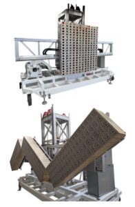
The PPE solar simulator frame’s pantographic morphing array of three balanced pivoting segments houses nested pLEDss heads in the open slots. Source: Bell-Everman
To accommodate these forces, we used heavier-than-usual linear bearing rails and crossed roller bearings with an 8-in. bore to pass Ethernet communication and 40 kW of electrical power per segment.
The array and morphing structure represent a 3,500-lb. cantilevered load on the vertical tower, requiring a counterbalance to both balance moment loads on the tower and provide something close to neutral buoyancy.
Gross movement of the combined payload and LED array is provided by a 10,000-lb. drum hoist. To achieve vertical motion, a single ServoBelt Heavy Linear is used with Bosch Rexroth drives and large redundant cables.
The counterbalance design ensures that the vertical drive only sees a weight imbalance of 50 to 300 lb. — more than enough breathing room for the ServoBelt Heavy LoopTrack drive, which can accommodate up to 600 lb. of linear force.
Also, thanks to the counterbalance, any drive failure would not result in dropping this valuable load. Threading these cables through pulley redirects enables the counterweight and payload to be raised together to their mid-height from a parked position at the bottom.
This interesting and fully redundant cable layout allows full neutral buoyancy throughout the range of the coarse positioning hoist.
Tower constructed piece by piece
The vertical tower supporting the solar simulator load will reach three stories high when fully constructed. Because it was too tall to fit inside the building where it was made, the tower was built in three pieces.
We made a shorter counterbalance cable set to allow the bottom section to be used for full functional testing within the low ceiling of our assembly bay.
As the lift travels up the completed vertical tower, any vibrations induced by imperfections where each section is connected would affect the simulator performance and diagnostic quality. We joined each tower section with a special multigenerational method of splicing, similar to our long-travel gantry systems. These universal splicing joints enable smooth vertical motion across the splices.
Z-axis automation for getting around
The motion system’s actuation is manually operated except for the Z-axis travel, which is fully automated. Because of the high value of space-going solar arrays like this, it is far better to manually move axes of motion that have any chance of damaging the array.
An electric-powered tug pulls the entire system for large movements, including when the system is removed from or put into storage. When the system is brought near the PPE solar array, fine adjustments are made with lever arms attached to the system’s wheels. When the correct position is achieved, screw feet are lowered to the floor.

Fully constructed, the solar simulator tower reaches three stories. Here, the pantographic morphing array is show in its six-by-six-foot configuration. Source: Bell-Everman
Electrical system designed to avoid flames
Because the simulator houses 240 of the 500-watt pLEDss heads, a large challenge of this project was managing over 120 kW of power.
Featuring many breakers and branches, the electrical system is designed to prevent overheating and fire damage should shorts occur at any level.
Calibration system is separate
To ensure that Angstrom Designs’ programmable LED solar simulators (pLEDss) perform successfully, they must be calibrated against solar cell standards called isotypes.
We also designed a calibration system for the PPE solar simulator to test against, consisting of an I-format gantry that houses the solar cell isotypes.
Known as the “Calibot,” this I-frame gantry robot is capable of calibrating the pLEDss heads while the system is in either morphing position.

pLEDss heads have full spectral control to current match junctions for cells from single junction up to six junctions. Source: Angstrom Designs
When the Calibot is maneuvered to the pLEDss tester, control boxes are linked, and docking mechanisms preserve the optimum standoff distance during calibration. Both the PPE simulator system and the Calibot will be stored with NASA in the same facility.
The pantographic morphing array consists of three smaller subarrays that each contain 80 pLEDss heads. Each subarray has its own terminal blocks and cables.
Each head’s DC power supply is delivered 220 VAC to allow the use of smaller 18-gauge power wires. Because of the amount of harnessing, it is important to reduce weight and space for the nearly 400 cables running to the breaker boxes.
Based on the early I-format gantry design — which needed to make a U-turn around the support scaffold holding two solar arrays, a floor mounted cable track and a guide system — the total cost for the power delivery alone was estimated to be roughly $200,000.
Thanks to the mobile-robot gantry design with simple extension cordage, this expense was reduced to $6,000 and only 150 feet of cable.
The entire project could have been accomplished with a large, track-based I-format gantry. But Bell-Everman simplified the design with mobile gantry robots, significantly reducing system complexity and costs.

I-Form linear robots featuring ServoBelt Linear actuators excel at point-to-point motion control. Source: Bell-Everman
The post Robots raise the bar for Artemis Program’s PPE solar array simulation frame appeared first on The Robot Report.
View Source


